Adapting/Connecting to the feed cable

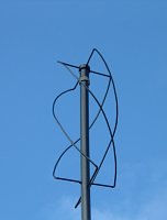
The QFH consists of two loops. To obtain a circular polarization,
it is necessary that the currents in both loops have a phase difference
of 90 degrees. Though it is possible to make the phase difference
with a phasing line (which is popular with the turnstile antenna),
the most popular solution for the QFH is to use different loop sizes.
This causes the current to be inductive in one, and capacitive in the
other.
Though the currents in both loops are reactive, connecting them in
parallel causes the feedpoint, at the top, to be at nearly 50 Ohm,
resistive.
The only problem remaining, is that the feedpoint, as with most antennas,
is symmetrical. This means we shouldn't connect a coax cable (asymmetric)
at this point. Though the antenna will be adapted, currents on the
outside of the cable will offset the radiation pattern of the antenna.
Several solutions exist:
- Transformer
We could install a balun transformer at the top, but simple baluns
transform impedance too - we want to maintain 50 Ohms.
- Choke
Applying a couple of turns to the coax cable at the top will make
the braid act as an RFC choke and block outside currents.
- Infinite balun
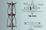
Feeding the cable through one of the loop sides, will form an
'infinite balun'.
- Preamplifier
Another - elegant - solution would be to install a preamplifier at
the top, and design it for symmetrical input. As far as I know,
none are on the market, so we'd have to make our own...
Finally, using simply two loops, without the strange 'twist' which is
so typical of the QFH, would generate a much more directional (vertical)
radiation pattern. Also, the polarization would turn to linear near the
horizon.
The 'twist' generates the desired hemispherical pattern, which
permits us to hear from horizon to horizon.
Choke baluns
 ON7EQ's QFH with balun
|
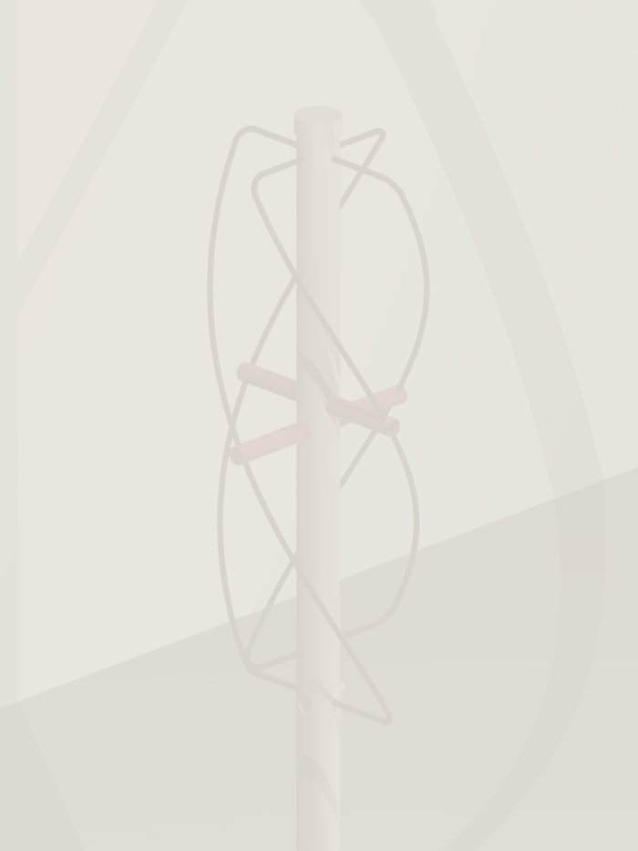
A simple solution for eliminating the exterior cable currents, is
to wind the cable a number of times around the vertical support,
making the outside act as an RF coke (inductor).
The diameter should be as small as is practical, to reduce radiation
as much as possible. The number of turns depends on the diameter,
of course, but the inductance should be large enough (compared to
50 Ohm) to reduce the outside currents.
The windings should be as near to the top as possible, to reduce
the length of the radiating parts.
|
Infinite baluns
 Infinite balun
|
Many questions arise about the infinite baluns...
The impedance at the top is the one we want at the bottom too. So
we cannot tolerate impedance transformation through the balun. This
means we have to use a cable with the same impedance - else
there would be a transformation!
For UHF and SHF work, the most practical solution is probably to use
coax cable for the actual antenna itself. For lower frequencies, we
should use tubing, and feed a 50 Ohm cable through it.
Part of the infinite balun principle, the cable's braid should be
connected to the antenna at the bottom center. In practice I have not
been able to detect much difference.
|
|
(c) John Coppens ON6JC/LW3HAZ |
mail |


