
QFH
Introduction
Matching
Simulations
Dimensions
Groundplane
Related:
Simple helicoidal
Bending the copper tubing isn't that easy, particularly if one doesn't own the right tools (like me). I invented an improvised bending tool. It's quite important to avoid deformations in the tube - it's necessary to pass the feedline through it later!
Several people asked me to mention that a balun is necessary to feed this antenna (Nigel, G4ZAL being the most insistent one, hi). The antenna, being symmetrical, presents a balanced load to the feeder. In the images below, the solution is to push the cable through one of the tubes, from center below to the top, where the feed point is. This constitutes an 'infinite balun', and is the most simple solution. More sophisticated is the method adopted by ON7EQ (check his pictures). I doubt if the result is different. His motive was the impossibility to get his more rigid cable through the tubing!
|
Raw materials: 5 meters of copper 8 mm tubing (5/16").
|
|
|
|
The two parts cut to the lengths indicated by the calculator. |
|||
|
Example of the bending of the inner loop (the smaller one). Start
practicing with this loop, it doesn't have to pass the feedline, so
a little deformation is permitted.
|
|
|
|
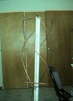
Side view of the almost terminated antenna - it's only missing the top cover. |
|||

|
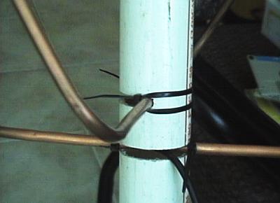
A view of the method used to fix the lower part of the loops.
Using a handsaw, I made a cut, just wide enough to receive the
tubing. I then fixed the tubes using cableties. It's not possible
to pass the tubes after bending, and bending the afterwards seemed
too risky...
|
|
|
|
Similar to the previous image - with a better view of the ties. Note that the coax cable enters the lower tubing at the middle. |
|||

|
Another side view of the completed antenna.
|
|
|
|
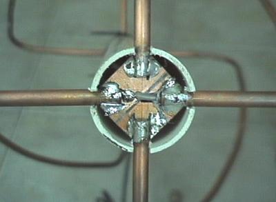
View from above. In the center, a small PC board can be seen, used to make the connections between the four tubes. Use fiberglass here! The pertinax boards don't stand the heat (literally). |
|||
|
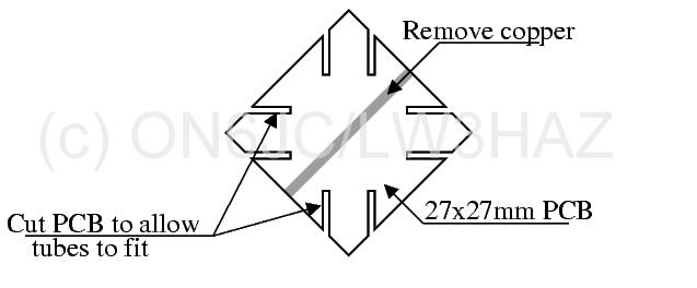
PC Board (fibreglass) prepared to receive the tube connections (top of
the antenna. Note the cuts to improve strength and ease soldering
|
|
|
|
Connections made to the PC board, and the tubes mounted. Of course the copper tubes should be soldered to the board! |
|||
|
Improved drawing for the connections at the top, and how to lead the
cable out at the bottom.
|
||
| (c) John Coppens ON6JC/LW3HAZ |