

Language:
Español
More info:
FAQ
Bibliography
Peperina team
Other kayaks
Links
Kayakers
Products

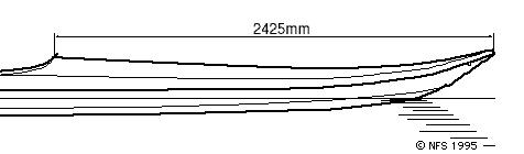
The exact location of the cockpit is a bit difficult. The original (Nick's) design indicates 2.42 metres from the front. I have the impression that 'my' design is a little longer and could justify moving it a few cm to the front (say at 2.38 m). Here's the original location:
To follow what happened then, check below.

|
This shows nicely the form of the plywood added to modify the original
opening.
|

|
|
|
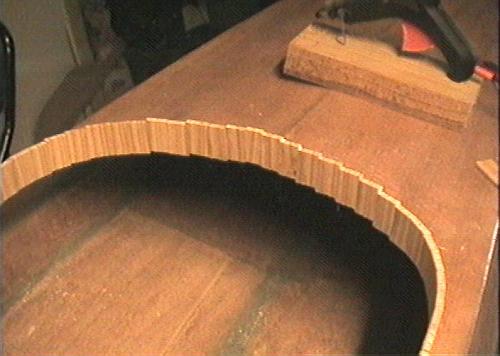
The form received its name from its similarity to a keyhole. It provides for knee support while paddling, and the large opening facilitates entering/exiting. |
|||

|
I used adhesive paper, marked the outer line to follow. Then I cut 120
5 cm long pieces of wood, about 6 mm thick, 19 mm wide.
|

|
|
|
Using fair amounts of patience, sandpaper, and handplaning, I adapted each piece of wood to the inclination. Each one is fixed with hot glue to the deck, and using carpenter's glue to each other. |
|||

|
To adapt the form, where the strips are above the deck, mark the correct
inclination...
|

|
|
|
... then cut it and glue it on. Note that, while most are glued to the deck from the inside, in the knee support area, they are just 'sitting' on the deck. |
|||

|
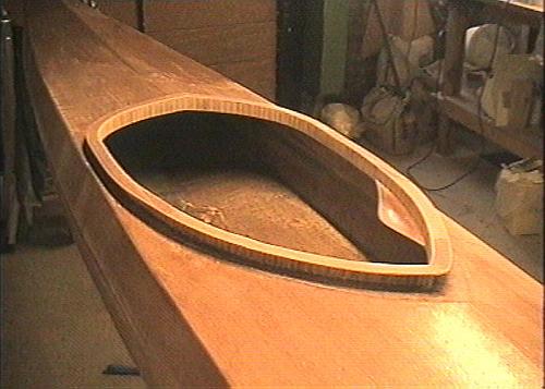
And a good while later... No too bad, isn't it?
|

|
|
|
A side look at the masterwork... |
|||
|
Ready! Of course, the last ones but be adapted in width to fill correctly
the last remaining space.
|

|
|
|
After the glue dried, I used a handsaw, with its blade turned 90 degrees, to cut the border evenly. I cut 17 mm above the deck. Though I guessed this value, it seems well inside the margins I found later in the books. Below deck, sand the border to get ir flush with the deck. |
|||
|
Next the upper border. As a result of the hybrid inlay I invented, the
border is a bit more complicated and consists of two different
inclinations. This border uses 4 pieces of plywood.
|

|
|
|
The aft section is easiest: it's just parallel with the deck. The picture shows the glued border (It's too large. I planned to cut it later). |
|||
|
The front part is more complicated, as it follow the hollow section inlaid
in the opening.
|

|
|
|
This is the union between both sections. The tape keeps the point aligned. |
|||

|
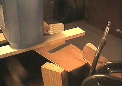
Everybody must help to keep the pressure! 20 litres keep the strip down.
|
|
|
|
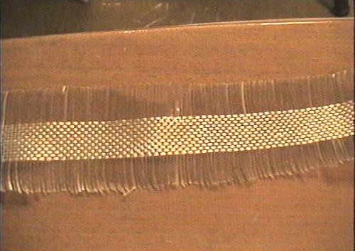
Glueing alone is not enough for all the forces this border will receive. I prepared a strip of fiberglass, with fibers removed to leave only enough to cover the vertical part. |
|||

|
The strip in place...
|

|
|
|
... and now saturated with epoxy. I should have filleted first - now I know! |
|||

|
Here's the strip completely installed, and the border ready to receive a
first coat of epoxy.
|
||
| (c) John Coppens ON6JC/LW3HAZ |