

Language:
Español
Technical data:
GOES
NOAA:
12 14 15 16 17
Meteor 3-5
Resurs O1-N4
Feng-Yun:
1 2
Other info:
Problems/FAQ
Links
Legend
Archive
Bibliography
QFH Antenna
Preamplifier
Wallpapers
Where are we?
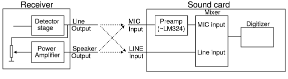 This is a block diagram of the audio system. Many receivers
have two outputs - LINE and Speaker. One is normally stable audio,
directly from the detector. The other (SPKR) is varied with the volume
potentiometer.
This is a block diagram of the audio system. Many receivers
have two outputs - LINE and Speaker. One is normally stable audio,
directly from the detector. The other (SPKR) is varied with the volume
potentiometer.
The sound card (or sound interface on the newer motherboards), normally has two inputs: MIC and LINE (or AUX). Sometimes more choices are available on cards.
4 possibilities to connect, as shown with the dotted lines on the above drawing. My preferences and considerations:
Always use the LINE output of the receiver, if available. The signal will normally be stable, unfiltered, and independent of the speaker level - important when the rest of the family is sleeping. The better quality of this output is the main reason though. If not available, use the speaker output, with the volume at about 30% (Less may give problems with cross-over distortion in the audio amp. More will almost surely introduce other problems). Mark the level on the receiver volume control.
The input on the computer is more difficult. I prefer the MIC input, because it's protected with an amplifier on the soundcard/motherboard. I've ruined at least one soundcard's LINE input through a direct connection.
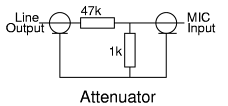
The MIC input has way too much sensitivity, so we need an attenuator to adapt the signal. See below for a circuit suited to connect LINE output to MIC input. For SPKR to MIC, use values 100 times lower - say 470 ohms and 10 to 22 Ohms. Put the attenuator at the computer side of the cable. This noticeable reduces problems with groundloops.
And finally, not all soundcards are created equal. In my experience, many of the chips included on the motherboard have serious flaws. I had been using my moboard sound interface quite happily for some time till I compared the results with an old Soundblaster card. I've seen cheap soundchips that do not even seem to convert the complete 16-bit promised (one had only 12 bits - 4096 levels instead of the promised 65536).
|
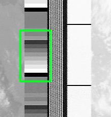
A good signal. All the steps are clearly visible in the sidebars of
the image.
|
|
|
|
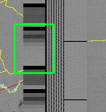
Not-so-good... Notice that about half of the gray steps are missing. The fact that the complete image is grayish, is probably because the decoding program is confused about what gain to use. The origin of the problem may be several things - the most probable being overload of the MIC input of the sound card. |
|||
|
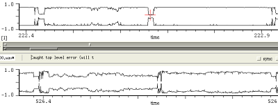
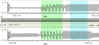
Here's a comparision between this last signal, and a comparable NOAA-15
signal correctly recorded. This is a complete 'line', with InfraRed to
the right. The almost complete saturation of the top signal is very
noticeable!
|
|
|
|
Here's a zoom of the above, near the sync pulses. The green and blue areas are still more enlarged below. |
|||
|
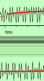
Sync pulse enlarged: Two errors can be detected in the top signal.
The top white pulses are noticeable wider than their counterparts
in the bottom signal. And the DC level (marked by the red line) shifts
because of the overload.
|
|
|
|
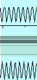
A bit more difficult to discern is the asymmetry of the signal. The top trace is more rounded at the top than at the bottom. It's also too rounded, as compared to the bottom trace. Another sign of saturation. |
|||
|
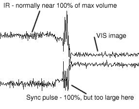
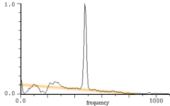
When the attenuator is too high impedance - or only one resistor
is used in series with the audio line - filtering effects occur. If you
check the signal and notice that the sync pulses are a lot larger than
the rest of the signal, that's a sure sign there's something wrong with
the spectrum. (The sync pulses have a component at 800 Hz which gets
amplified more that the 2400 Hz carrier).
|
|
|
|
Suspecting this problem from the view of the signal above, I asked the audio program to show the spectrum near a sync pulse. The orange line indicates a preference for low frequencies. |
|||
|
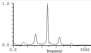
Here's a comparision with a clean audio system. The spectrum is
symmetric around 2400 Hz and nicely shows the components - again
symmetrically - of the sync pulse.
|
|
|
|
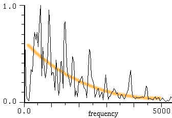
A final confirmation can be had, when observing a part from the audio where no satellite is present - just noise. The exaggerated preference for low frequencies is very noticeable here. Note that some receivers insert a low-frequency enhancement filter to compensate for a too small speaker. Another reason not to use the speaker output! |
|||
|
Suggested attenuator - the 1k resistor can be modified to
regulate the signal.
|
||
|
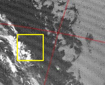
The behaviour of the sound card produces interferences on the
screen (both due to unlinearity and deviation from the 11,025 Hz
standard)
|
|
|
|
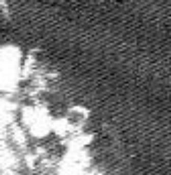
Enlargement of the yellow part, left. These lines are due to the unlinearities of the motherboard A/D |
|||
|
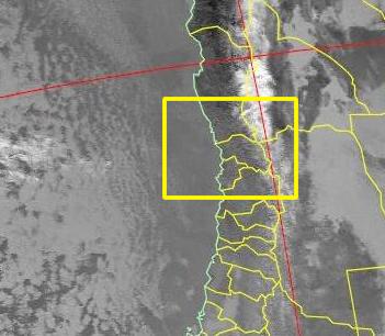
This is a similar picture, but using the old and reliable Soundblaster.
the interference is gone!
|

|
|
|
And so are the lines. This is a 400% enlargement of the yellow part left - no noticeable lines (some artifacts in the image are due to the JPEG compression) |
|||
| (c) John Coppens ON6JC/LW3HAZ |