Language:
Español
Reception:
QFH Antenna
Preamplifier
Original version
Converter
TDA7000 IF amp
'New' receiver
Other information:
Links
Legend
Archive
Bibliography
Wallpapers
Where are we?

1. An acceptable noise figure, but not worrying too much about it as I had plans to put a low noise amplifier at the antenna. So it's preferable to have an input stage which can handle a strong signal.
2. A mixer with a dual-gate FET. I tried several times to get a bipolar transistor mixer to work, but always hsa problems with strong signal handling.
3. A simple crystal oscillator (and multiplier). Thanks to the freedom of selecting the intermediate frequency, the crystal frequency wasn't critical.

|
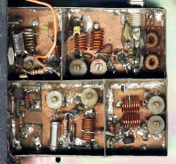
The left image shows the distribution of the different stages. I didn't
use a prepared circuit board - just a blank piece of PC material.
Shielding was done with 1" wide strips of tin, cut from cans.
The size of the complete converter is 60 by 68 mm. The current stabilization circuit for the input transistor resided at the left of the oscillator compartment. Some isles to mount components have been cut using a small drill. Note that this is not meant as a detailed construction guide. If you don't have at least access to a frequency counter, some way to measure Rf levels at 130 MHz, and a fair amount of experience at VHF, find another - more simple - project. Like any receiver, it's built in reverse: first the crystal oscillator which can be tested by itself, then the multiplier, tested, then the mixer, tested, and finally the RF amplifier + stabilizer. If you haven't built the IF part yet, you can test this converter by using your HF receiver as a temporary IF. This is not an apology for the untidiness of the circuit. It was actually designed in the order above, just started in one corner and built, stage by stage. Some parts have been re-built several times till I was more or less satisfied. |

|
The diagram of the converter. It's also available in PDF format for those who can't see PNG images yet. |
| (c) John Coppens ON6JC/LW3HAZ |