Language:
Español
Reception:
QFH Antenna
Preamplifier
Original version
New receiver
Converter
Bandpass filter
Other information:
Links
Legend
Archive
Bibliography
Wallpapers
Where are we?
Anyway, a fairly sharp Tchebyshev filter was designed, simulated and constructed, and, on the way, a lot was learned about LC-filters while building. Schoolbooks is one thing, making it work quite another...
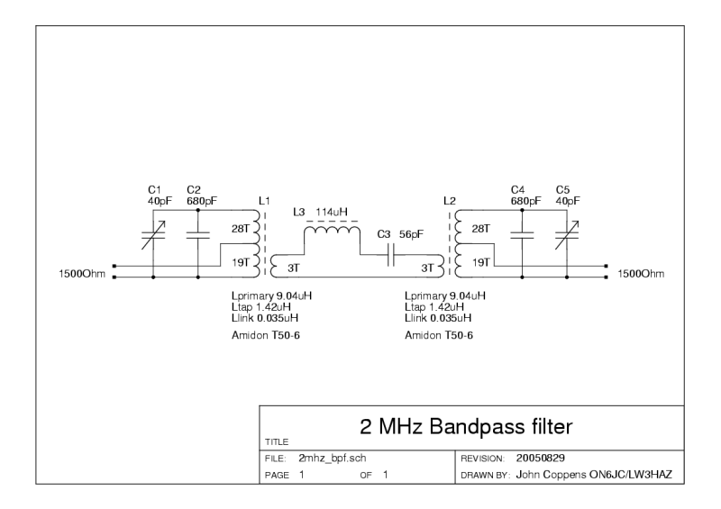
Click on the image to obtain a larger version. There's also a PDF version of the circuit. |
Left is the circuit of the bandpass filter. A few remarks about
strange things:
|
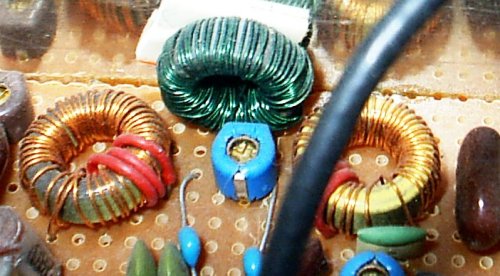
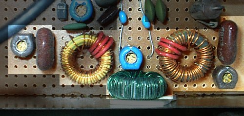
| One view of the filter. The blue trimmer C tunes the coupling section. The white thing behind the couple L is foam double-sided adhesive tape, to fix the toroid to the wall. |
|
| Another view. The black trimmer Cs at each end are the tuning caps. The brown caps are Mica 680 pF capacitors. |
|
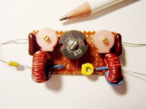
| This version was constructed by Jeff, VE3AK. He commented that the filter could not be measured using a function generator - it was too narrow! He used a potcore for the coupling inductor (center). |
|
|
|
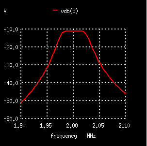
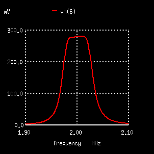
| Filter response in dB | Filter response (magnitude) |
Response of the filter, simulated with NGSpice.
8889
| (c) John Coppens ON6JC/LW3HAZ |